
Phasor Diagrams for Transformer on Load
Consider a transformer supplying the load as shown in the Fig. 1.
Consider a transformer supplying the load as shown in the Fig. 1.
 |
| Fig. 1 |
The various transformer parameters are,
R1 = Primary winding resistance
X1 = Primary leakage reactance
R2 = Secondary winding resistance
X2 = Secondary leakage reactance
ZL = Load impedance
I1= Primary current
I2 = Secondary current = IL = Load current
now Ī1 = Īo + Ī2'
where Io = No load current
I2'= Load component of current decided by the load
= K I2 where K is transformer component
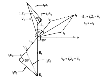
The primary voltage V1 has now three components,
1. -E1, the induced e.m.f. which opposes V1
2. I1 R1, the drop across the resistance, in phase with I1
3. I1 X1, the drop across the reactance, leading I1 by 90o

The secondary induced e.m.f. has also three components,
1. V2, the terminal voltage across the load
2. I2 R2, the drop across the resistance, in phase with I2
3. I2 X2, the drop across the reactance, leading I2 by 90o

1. Consider flux Φ as reference
2. E1 lags Φ by 90o. Reverse E1 to get -E1.
3. E1 and E2 are inphase
4. Assume V2 in a particular direction
5. I2 is in phase with V2.
6. Add I2 R2 and I2 X2 to to get E2.
7. Reverse I2 to get I2'.
8. Add Io and I2' to get I1.
9. Add I1 R1 and to -E1 to get V1.
2. I1 R1, the drop across the resistance, in phase with I1
3. I1 X1, the drop across the reactance, leading I1 by 90o

The secondary induced e.m.f. has also three components,
1. V2, the terminal voltage across the load
2. I2 R2, the drop across the resistance, in phase with I2
3. I2 X2, the drop across the reactance, leading I2 by 90o

The phasor diagram for the transformer on load depends on the nature of the load power factor. Let us consider the various cases of the load power factor.
1.1 Unity power factor load, cosΦ2 = 1
As load power factor is unity, the voltage V2 and I2 are in phase. Steps to draw the phasor diagram are,1. Consider flux Φ as reference
2. E1 lags Φ by 90o. Reverse E1 to get -E1.
3. E1 and E2 are inphase
4. Assume V2 in a particular direction
5. I2 is in phase with V2.
6. Add I2 R2 and I2 X2 to to get E2.
7. Reverse I2 to get I2'.
8. Add Io and I2' to get I1.
9. Add I1 R1 and to -E1 to get V1.
Angle between V1 and I1 is Φ1 and cosΦ1 is primary power factor. Remember that I1X1 leads I1 direction by 90o and I2 X2 leads I2 by 90o as current through inductance lags voltage across inductance by 90o. The phasor diagram is shown in the Fig.2
 |
| Fig. 2 Phasor diagram for unity power factor load |
Lagging Power Factor Load, cos Φ2
As load power factor is lagging cosΦ2, the current I2 lags V2 by angle Φ2. So only changes in drawing the phasor diagram is to draw I2 lagging V2 by Φ2 in step 5 discussed earlier. Accordingly direction of I2 R2, I2 X2, I2', I1, I1 R1 and I1X1 will change. Remember that whatever may be the power factor of load, I2X2 leads I2 by 90o and I1X1 leads I1 by 90o.
The complete phasor diagram is shown in the Fig. 3. |
| Fig. 3 Phasor diagram for lagging power factor |
Loading Power Factor Load, cos Φ2
As load power factor is leading, the current I2 leads V2 by angle Φ2. So change is to draw I2 leading I2 by angle Φ2. All other steps remain same as before. The complete phasor diagram is shown in the Fig. 4
 |
| Fig. 4 Phasor diagram for leading power factor |
Sponsored links :
Very good information!!!! Thank you, Erik Arckens
ReplyDeleteThanks. U're Awesome :)
ReplyDeletethere are two inductances on primary side one is that of Py winding and other due to leakage reactance. lenz's law is applicable on both inductors.i.e there should be -ve sign with E1 as well as I1X1 drop. but we have used with only E1 not with the other inductor.please explain with very basic concepts so that I can get the idea.further with applied signs both should be voltage drop across the inductor and should have same sign?
ReplyDeleteplease post the picture of phasor diagram of ideal transformer with capacitive load
ReplyDeleteNice information
ReplyDeleteThis was really helpful... Thank u so much.
ReplyDeletePlease explain the expression for volt ampere and reactive volt ampere in three phase system
ReplyDeleteLife is full of many challenges. Challenges that will make you or break you depending on how you handle it. Visit my site for more updates. God Bless to your site.
ReplyDeleten8fan.net
www.n8fan.net
Sir, In the practical transformer case, what is criteria for drawing the V2 phasor? How much angle the V2 phasor is lagging or leading the E2 phasor?
ReplyDeleteSir, actually V2 is not leading or lagging by E2 because two voltages never leads or lags behind / over themself.
DeleteActually V2 is drawn as per our load conditions
Let me clear....
I2 is drawn as reference of I2'and than V2 is drawn as per the load condition. (Lagging/leading/unity).
If our load is lagging than we draw V2 leading by I2 (or I2 lagging by V2), If our load is unity than V2 is in phase of I2 , If our load is leading than draw the V2 lagging by I2 (or I2 leading by V2). As shown in phasors.
Toroidal winding machine has included changing parameters with the support of controller unit and this is multi-reason joined controller. The structure can be changed to pass on the sensible application for focal application. So in like way, the toroidal winding machine has contained with standard stepper motor drive, DC motor drive, and power supplies in a control box. All around, this kind of winding machines has controlled for transformers. Bobbins
ReplyDeleteAnother material is kool mu is sensible cost and it has demonstrate the lower loads and in a general sense goliath warm properties when related with controlled iron obsession interests. The kool mu is key use when the high flux thickness and low fixation stacks fittingly figure change circuits same as unidirectional drive application like pulse transformer and flyback transformer.toroidal transformer winding machine
ReplyDeleteThe running with kind of circle winding machine is set up with spool, bobbin and some stunning materials and it would be apply specific endeavors. As a last resort, the circle winders can sorted in setting of most overwhelming and its speed levels. The turn winding machine speed levels has moved the most difficult to miss and execution.Miniature Winding
ReplyDeletehttps://tubeless12.blogspot.in/2018/05/how-to-reach-allen-sankalpa-kota.html?m=1
ReplyDelete